In this Article
- Rethinking the Propel’s Integrated Cockpit
- How the Propel Routes Its Brake Hoses
- Tools and Torque for a Carbon Front End
- Moving the Split Spacer Stack
- A River Trail Aero Drop, Step by Step
Rethinking the Propel’s Integrated Cockpit
An integrated front end looks permanent when you first see brake hoses disappear beneath an aero stem. On a current Giant Propel Advanced with the two-piece aero bar and stem, the split-spacer stack gives you a useful way to test handlebar height. Its interlocking composite spacers allow changes in 2.5mm and 5mm increments, and you can move them without opening the hydraulic system.
That changes the fit conversation. A rider who feels stretched toward the hoods can try a small height change, ride a familiar local route, and compare wrist pressure and breathing before making a permanent cut to the steerer. A rider chasing a lower position can make the same kind of measured test. The value lies in being able to reverse the adjustment.
This walkthrough applies to 2023 and newer Propel Advanced framesets with the two-piece aero system. Earlier Propel front ends used a more enclosed monocoque arrangement and require a different approach, including hose disconnection for changes that this split-spacer system permits. Check which front end is on the bike before loosening anything.
There is still a boundary between a home fit adjustment and brake work. Keep the hoses connected, watch their slack throughout the change, and stop if the stem will not move freely. Those habits matter more than how quickly the spacers come apart.
How the Propel Routes Its Brake Hoses
The D-shaped steerer explains both the cleverness and the care this job demands. Its flattened rear section creates a 12mm channel for the two hydraulic hoses. From the Contact SLR or Contact SL aero handlebar, those hoses pass through the proprietary stem’s routing channel and continue beside the steerer into the frame. The tidy view from above hides a fairly crowded junction.
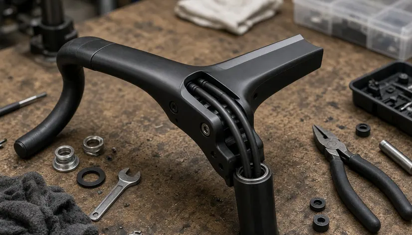
Think about the bar and stem as separate fit controls. The stem sets the bar’s location relative to the steerer. Because the faceplate holds the handlebar, loosening it lets you roll the bar for wrist position while the stem retains its aero shape. Rotation of up to 3 degrees, upward or downward, stays available on the two-piece arrangement without exposing the cables to the wind, provided the hoses remain free through the movement.
That independence is useful when a rider likes the hood height but finds the wrist angle awkward. Changing stem stack would move the entire hand position; a small bar roll addresses a different problem. Mark the starting bar position before loosening the faceplate, make one change, and check access to the brake levers from the hoods and drops.
The hose channel also sets a practical test for every adjustment: turn the bars and observe what happens at the front end. A hose that becomes taut, rubs hard at the channel entrance, or tugs the bar back toward center needs attention before the bike goes out on the road.
Tools and Torque for a Carbon Front End
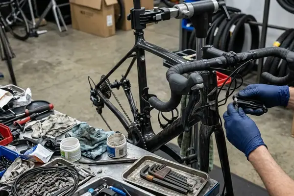
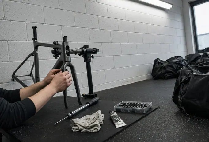
Set out the tools before touching the top cap. You need a calibrated micro-torque wrench that covers the specified settings, high-quality hex bits that seat fully in the bolts, and carbon assembly paste for the steerer clamping surface. Clean mating surfaces make it easier to see what you are tightening and keep grit out of the clamp.
Before the First Bolt
- Verify that the micro-torque wrench covers the 2.0 to 5.5 Nm range and is calibrated.
- Confirm that the hex bits fit the top-cap, faceplate, and stem bolts without play.
- Apply fresh carbon assembly paste to the steerer clamping surface.
- Check that both hydraulic hoses have slack for the stack-height change you intend to test.
For this setup, the stem faceplate has a 5.5 Nm maximum. Tighten its bolts evenly so the faceplate settles squarely against the bar. The steerer clamp pinch bolts call for alternating quarter-turns until each reaches 5.2 Nm. That alternating sequence keeps one side from drawing down while the other remains loose and concentrates pressure on the carbon steerer.
Read the markings and instructions for the actual bar and stem in front of you before applying these settings. Hardware can differ even when two cockpits look alike. If a component carries a different specified limit, resolve that difference before tightening it.
Carbon clamp damage often begins with a small, well-intentioned extra turn after the wrench has reached its setting. Resist it. The top cap has a separate job: it preloads the headset bearings before the stem clamp secures the position. It is not a substitute for the pinch bolts. Keeping those jobs distinct protects the steerer and makes headset adjustment easier to judge.
Protect the Hose Channel
Keep hex bits, spacer edges, and clamping pressure clear of the hydraulic lines. If a hose appears pinched or its movement changes as a bolt tightens, stop and inspect the routing before riding.
Moving the Split Spacer Stack
Start with the bike steady and the front wheel supported. Note the current spacer order and stem height, then loosen the top-cap compression bolt and the stem pinch bolts. The stem should now move without fighting headset preload. Support the handlebar as you work so its weight does not pull on the hoses.
Each interlocking composite spacer separates laterally into two halves with a gentle outward pull. That is the key to the adjustment: the halves come away from the steerer without requiring you to thread an intact ring over the routed hoses. Keep track of how they interlock so they go back together cleanly above or below the stem.
I once tried removing three 10mm spacers at the same time to reach a lower position quickly. The excess hose length bound up inside the head tube. Since then, a single 5mm or 10mm change has been the useful unit of work: move one spacer, gently guide the available hose slack into the frame cavity, and check for neutral hose tension before going farther. That sequence also makes the fit test easier to interpret.
- Separate the chosen spacer’s halves and lift the stem only as much as the hoses comfortably allow.
- Reassemble that spacer above the stem, keeping the stem’s clamp fully engaged on the steerer.
- Confirm that the top-cap and upper-spacer arrangement can compress the headset without bottoming out.
- Tighten the top-cap compression bolt to the specified 2.0 to 2.5 Nm range, checking that the headset turns smoothly without play.
- Align the stem with the front wheel. Tighten the steerer pinch bolts in alternating quarter-turns to 5.2 Nm.
Before riding, apply the front brake and rock the bike gently to check for headset play. Then turn the bar through its available range and watch the hoses where they enter the stem. If the steering binds or a hose pulls taut, reopen the adjustment and restore slack. Leave the steerer uncut while you test the new height on the road; the spacer above the stem preserves an easy path back to the previous setting.
A River Trail Aero Drop, Step by Step
Picture a Propel Advanced rider preparing for fast, flat efforts on the 14-mile stretch of the Arkansas River Trail between the Big Dam Bridge and Clinton Presidential Bridge. The rider already likes the bar’s rotation and hood angle, so the test changes stack height alone. A single 10mm spacer moves from beneath the stem to above it, lowering the hands and encouraging a lower torso angle.
- Record the starting position. Check the existing spacer stack, mark the stem’s alignment with the front wheel, and confirm that the hoses have room to move. Leave the handlebar faceplate alone; bar roll is not part of this test.
- Release the stack. Loosen the top cap, then loosen the stem pinch bolts. Support the bar and raise the stem just enough to reach one 10mm split spacer underneath.
- Move one spacer. Pull its interlocking halves gently away from the steerer, lower the stem, and rejoin the halves above it. Guide hose slack into the frame cavity without forcing a bend or trapping a line at the stem channel.
- Restore preload and clamp. Check that the stem remains fully engaged on the steerer and that the top cap can preload the headset. Set the top cap within 2.0 to 2.5 Nm, align the stem, then tighten its pinch bolts in alternating quarter-turns to 5.2 Nm.
- Check before the trail. Apply the front brake and rock the bike to check for headset play. Sweep the bar roughly 45 degrees left and right, confirming zero hydraulic-line tension. Squeeze both brake levers, then take a short, easy ride and repeat the steering and headset checks.
Now ride the same flat stretch in the new position and pay attention to whether the rider can hold the hoods comfortably through the effort. Keep the 10mm spacer above the stem during the test. If the lower position works, the rider has a repeatable setup for the next River Trail session; if wrist pressure rises or steering feels restricted, the split spacer can go straight back beneath the stem using the same sequence.